水处理常用计算公式汇总,从格栅到工艺计算都全了
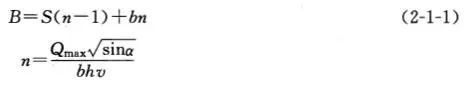
格栅的设计计算
(6)大中型格栅间内应安装吊运设备,以进行设备的检修和栅渣的日常清除。
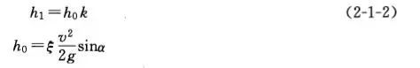
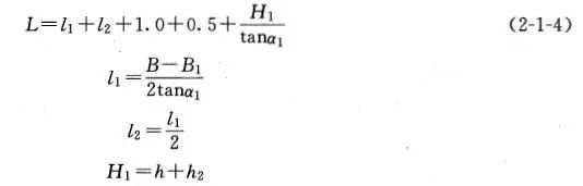
二、格栅的设计计算

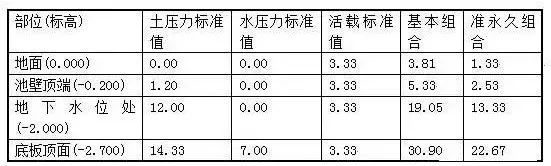
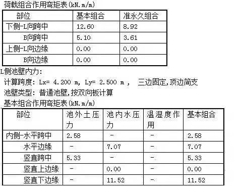
一、地基承载力验算
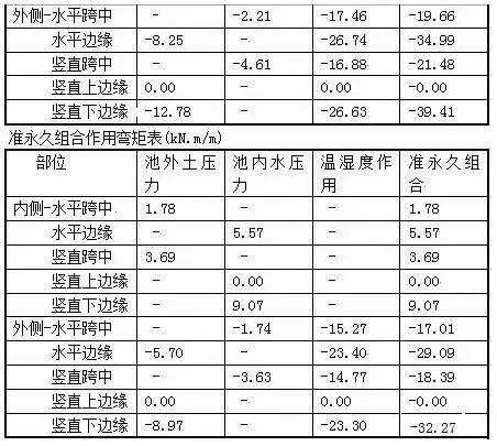
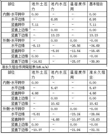
三、荷载计算
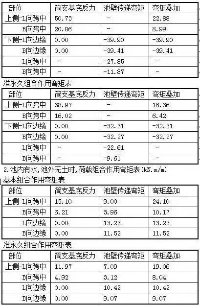


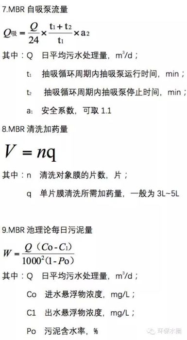
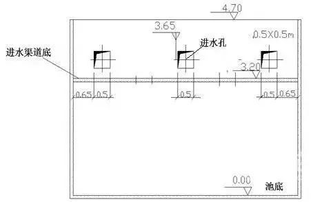
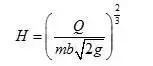
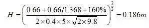
一、曝气池的进水设计
文章内容来源环保小蜜蜂、环保水圈,图片来源:环保水圈,转载平台:环保小蜜蜂微信,责任编辑胡静,审核人:李峥
版权声明∶转载流程工业网内容,请在正文上方注明来源和作者,且不得对内容作实质性改动;微信公众号、头条号等新媒体平台,转载请联系授权。邮箱∶process@vogel.com.cn,电话:16601379371(同微信)
相关推荐
-

-

石油化工废水处理流程设计及工艺改造
石油化工废水中主要污染物一般可概括为烃类、烃类化合物及可溶性有机和无机组分。其中,可溶性无机组分主要是硫化氢、氨类化合物及微量重金属;可溶性有机组分大多能被生物降解,也有少部分难以被生物降解,或不能被生物降解,如原油、汽油和丙烯等。
2022-09-28
-


热点文章
-

国企推进 CCUS 技术攻关与示范项目建设
2026-06-30
-

重磅新闻丨CIEI 2026盛大开幕!具身启元,智创未来,共赴智能新纪元
2026-07-03
-

《国内外投资可持续航空燃料SAF态势》前言&目录
2026-07-03
-

恒逸石化2026上半年业绩爆发,净利同比最高增2546.88%!
2026-06-29
-

总投资590亿元,内蒙古大型煤化工项目最新进展
2026-06-18
-

《合成纤维与生物纤维及其应用》序言&目录
2026-07-07
-

总投资802.9亿元,延长石油千万吨级炼化一体化项目有新进展
2026-07-06
-

工业企业“碳中和”实践之路
工业是节能降碳的重点领域,也是实现“3060”碳达峰碳中和目标的关键。党的二十大报告明确提出,积极稳妥推进碳达峰碳中和,推进降碳、减污、扩绿、增长,完善能源消耗总量和强度调控,重点控制化石能源消费,逐步转向碳排放总量和强度“双控”制度。为了回顾 2023 年工业企业在节能降碳、绿色可持续发展方面的成就,了解当下的创新技术和应用,《流程工业》编辑部在 2024 年第一期特别策划了“工业碳中和”专题,邀请了一批国内外优秀的工业企业分享观点和产业实践,为广大的流程工业企业提供绿色可持续发展的启迪和借鉴。
作者:
-
2025国内外石油开发、生产与需求述评-目录
-
以开放自动化与AI双轮驱动,定义中国未来工业新范式
-
视频 │ 煤化工如何实现从“黑”到“绿”?走进美锦能源低碳发展标杆项目
-
智能运维让设备”说话“,德姆斯护航企业安全生产与降本增效
-
2024上海国际泵阀展现场,《流程工业》记者专访了中国善若泵业科技有限公司总经理 卢阳


评论
加载更多